System Architecture & Design Overview
- Software Design
- Done by Software Design Engineer OR UI/UX Designer
- first step in SDLC, which moves the focus from problem domain to solution domain.
- The process can be divided into three levels of designs
- Interface Design
- Architectural Design
- Detailed Design
Software Quality Attributes
- FURPS
- Functionality
- Usability
- Reliability
- Performance
- Supportability
Software Design Concepts 1. Abstraction -> Hide unnecessary Details | Procedural and Data abstraction 2. Architecture -> structure of program modules where they interact with each other 3. Design Patterns -> 4. Modularity -> Dividing system or project into smaller parts to reduce complexity | Modules integrated together later for working application 5. Information Hiding -> Design modules such that data structures and algorithm details of one module are not accessible to other modules. 6. Functional Independence - Concept of separation and related to modularity, abstraction and information hiding. - Two Criterias : Coupling and Cohesion - Coupling - Degree in which module is connected to the other module - Low coupling means a good software - Cohesion - Degree in which module performs functions in the inner module in the system - High cohesion leads to a better software. 1. Refinement -> breaking down high level concepts into low level and even that till code statement levels. 2. Refactoring -> process of changing the internal software system in a way that it does not change the external behavior 3. Object-Oriented Design Concept -> faster, low-cost development and creates a high-quality software.
Coupling - degree of interdependence or number of relations between software modules. - modules that are tightly coupled are strongly dependent on each other. - A good design is the one that has Low coupling. - High coupling generates more errors because they shared large number of data. - Coupling Types 1. Content Coupling -> Share same content like functions, methods | when one module updated all other need to be updated 2. Common Coupling -> Share info through some global data items 3. External Coupling -> Share an externally import data format, communication protocol or device interface 4. Control Coupling -> handles functional flow between software modules. | Module 1 sets a flag to allow module 2 to perform operations 5. Stamp Coupling -> stamp coupled if communication between is modules uses composite data items such as Complete Data structure & objects | No junk/unused data shared between the modules 6. Data Coupling -> Data is poassed from one module to another module via argument list or parameters through functional blocks
1 is considered the worst, whereas 6 is considered the best out of the above mentioned couplings.
Cohesion - Degree to which the elements of a module belong together or interrelated. - Measures the strength of relationships between pieces of functionality within a given module. - Good design will have higher cohesion - Types of Cohesion 1. Coincidental -> Performs a set of tasks associated with each other very loosely. | Example: Calculator: ADD, SUB, MUL, DIV 2. Logical -> If all Elements of module perform similar operation 3. Temporal -> Activities related in time, wheere all methods executed at same time | Found in the modules of initialisation and termination | Example: Counter = 0, Open student file, Clear(). Initializing the array etc. 4. Procedural -> parts of a procedure execute in particular sequence of steps for achieving goal. | nested function calls but in the same module 5. Communicational -> all elements are working on same I/O data and are accessing that data through the same data structures | Example: Update record in the database and send it to the printer. 6. Sequence -> one elements output redirected to other element as input in the same module. 7. Function -> functional cohesion is single minded, high, strong and focused. | single module aims to perform all the similar types of functionalities through its different elements. | E.g. Railway Reservation System
Design Models - There are four types of design elements/models 1. Data Design Element / Model 2. User Interface Design Element / Model 3. Architectural Design Element / Model 4. Component Level Design Element / Model - Architectural Design Model - Set of hardware & software components that will perform a function required by the system. - Eg. Database, Modules, Frameworks etc. - serves as a blueprint for a system. - The architecture focuses on the early design decisions. - A software architecture can be defined in many ways : - UML (Unified Modeling Language) − UML is one of object-oriented solutions used in software modeling and design. - Architecture View Model (4+1 view model) − Architecture view model represents the functional and non-functional requirements of software application. - ADL (Architecture Description Language) − ADL defines the software architecture formally and semantically. - Importance of Software Architecture 1. Security 2. Performance 3. Maintainability 4. Safety 5. Availability
UML - It is a pictorial language used to make software blueprints. UML was created by Object Management Group (OMG). - Unified Modeling Language - described as a general-purpose visual modeling language to visualize, specify, construct, and document a software system. - Further Divided into Structural Diagrams and Behavioral Diagrams - The elements are like components which can be associated in different ways to make a complete UML picture, which is known as a diagram.
- Structural Diagrams
- Represent the static aspects of a system.
- represent those parts of a diagram which forms the main structure and is therefore stable.
- Behavorial Diagrams
- Behavioral diagrams basically capture the dynamic aspect of a system.
- Dynamic aspects are basically the changing/moving parts of a system.
- Examples -> Use Case , Sequence Diagram
4+1 View Model
- A multi view model that addresses different features and concerns of the system.
- Standardises the software design documents and makes the design easy to understand by all stakeholders.
- Essential Views it provides:
1. The logical/conceptual view
2. The process view
3. The physical view
4. The development view
- This view model can be extended by adding one more view called scenario view or use case view for end-users or customers of software systems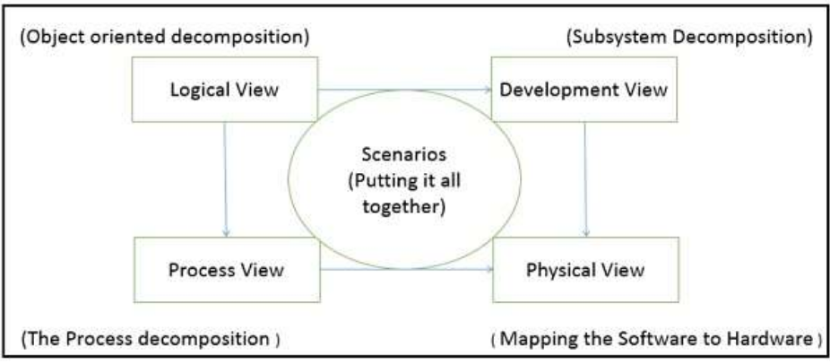
4Ps -> People, Product, Project, Process - WWWWWHH Questions: 1. Why? 2. What? 3. When? 4. Who? 5. Where? 6. How? 7. How Much?
// TODO